I guess, most of the riders want to install additional electrical devices on their bikes. So I will explain in this tutorial, how to connect them properly and to make sure, that they are disconnected from the battery as soon as you turn off the bike.
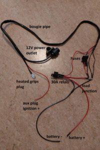
I made a new cable harness for all our devices. All the cables lead through a bougie pipe to give them some additional protection and a clean cable run without having single cables running around everywhere.
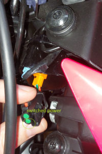
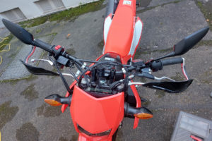
One cable is for switched power coming from the AUX 12v accessory connector on the front right side behind the headlight (see left photo). Either buy a connector that fits the stock connector or just solder the cables. It is connected to a 30A relais, that interconnects all the devices when the bike is turned on by the ignition switch (key). Like that you make sure, that no device drains your battery when the bike is turned off. Some devices might have a battery control function e.g. Oxford heated grips, but I still feel on the safer side by doing so. The cable harness you see on the right photo includes Oxford heated grips and a 12V power plug (I’m going to install a GPS later on, too). Of course, you can add more electrical devices – just ensure, that you don’t drain more power than your bike’s alternator can produce + the weak point of the cable harness is the relais with 30A max. So don’t burn it!
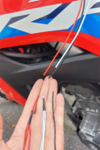
All device power cables (red) have individual fuses and join before the relais. All earth/mass cables (black) join after the bougie pipe. I used ring cable shoes hold together by a short screw and a nut. Like that you can easily add other devices in the future. However, ensure to isolate them before usage (don’t use them as shown on the photo). Flat connectors are used for the relais. All connectors are crimped, soldered and isolated with heat shrink tube. In the end we have only a single power cable (red) and earth cable (black) to connect to the battery. These single cables + the red single cable after the joint are in 4 mm² conductor cross section. So they can stand more power than the 30A relais.
Like you might have already read in our heated grip tutorial, I removed all its connectors and soldered them together. If you don’t want to do that, buy some weatherproof connectors or the Oxford EVO grips instead. They already come with weatherproof connectors. When you cut the bougie pipe coming from the heat controller, you can see, that the cables are split inside into 2 cables to connect the grips. In case you decide to solder the cables, you can cut these cables. That makes it easier to solder, too.
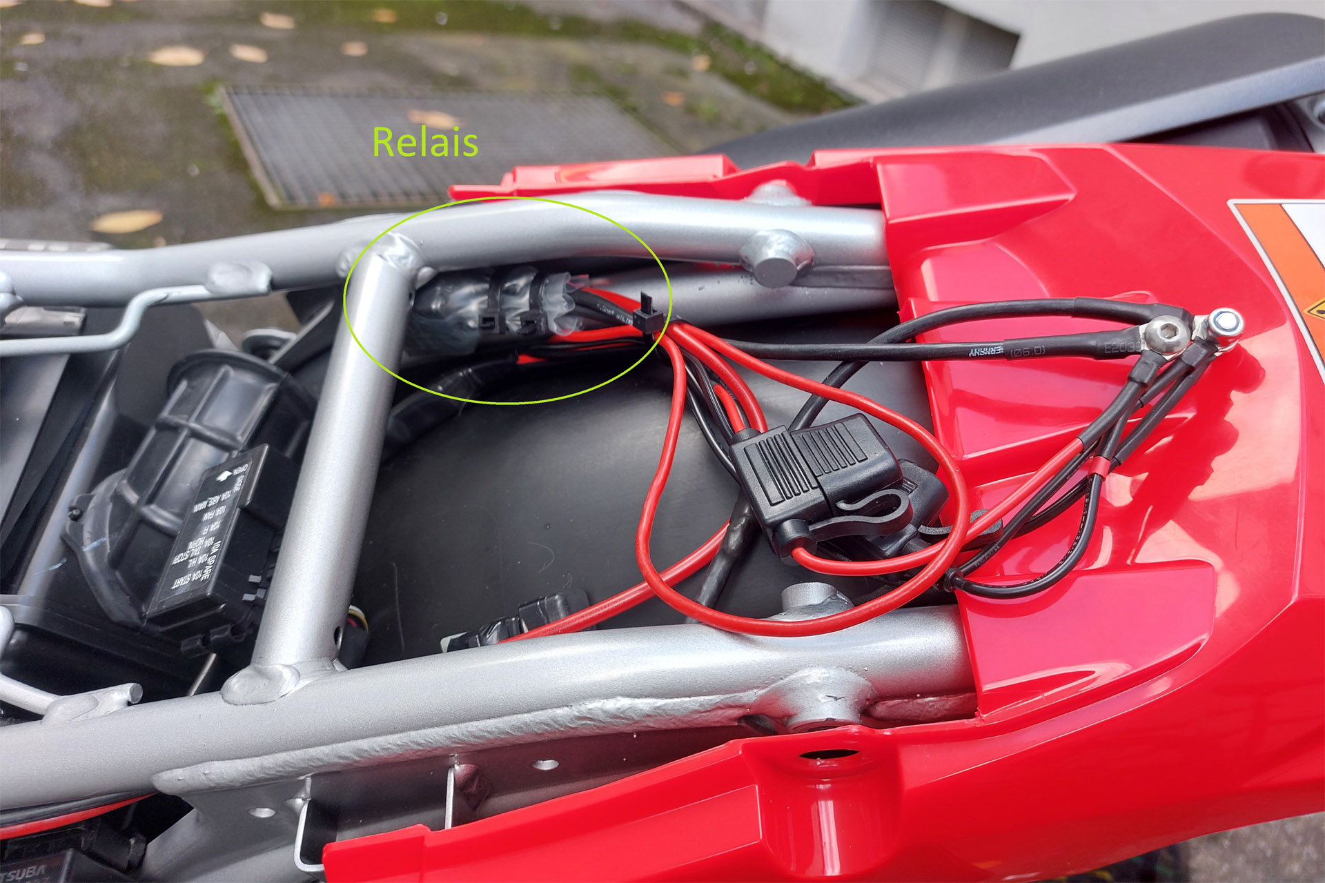
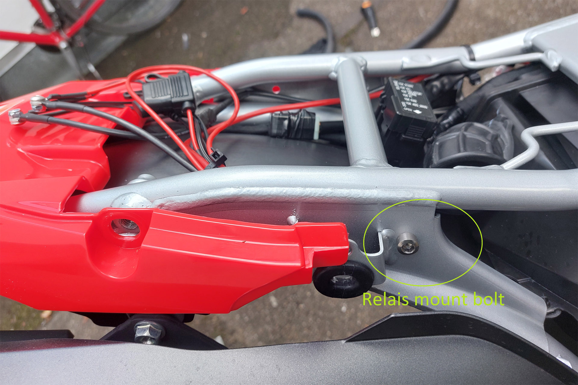
I found a good place for the relais under the seat close to the air intake. There is a screw hole in the metal sheet of the subframe. The relais connectors were isolated with self sealing tape and shrinked in some heat shrink tube. I mounted the relais with a stainless steel screw + a stop nut. Attention with the photo in the midle! Of course, you can’t leave the cable joints like that, if you want to use your bike. Make sure to isolate them. Since I’m going to install an additional GPS device soon, I haven’t isolated them yet.



What is the stator output on the CRF300L. I have a ‘23 and wondering if I can run a heated jacket.
Hi, I’m not 100% sure, but for the CRF250L it was around 300W. So I guess it is pretty much similar.
That AUX connector behind headlight is NOT powered by 30A relay. It is powered by 10A “start” fuse that also supplies power to dashboard and ignition switch that controls these 30A relays (but each relay switches only 10A fused circuit). So if you blow this “start” fuse, you also lose control power to FI relay, fan relay a starter relay, effectively disabling your motorbike. Honda rates this AUX connector for max 3A.
I would avoid using that connector, instead tap switched power from some non-essential switched fuse. I’ve tapped ABS control unit fuse for my heated grips as ABS is the least needed part of motorbike.
Hi, the connector is only used to switch the relay for all other devices. So there is not much load on that front AUX connector.
Thank you for sharing this information! If you need some details about Website Promotion than have a look here UY9